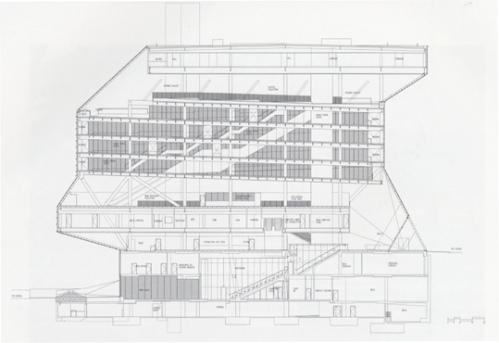
Here the Seattle Central Library is represented by a cross section throughout the entire building. These documents are usually created to describe the vertical interactions between spaces, which combined with the plan drawings allows for a three dimensional perception and abstraction of the spaces. Considering the binary system of compartmentalized flexibility at play in this building, this technical drawing allows to better understand the vertical articulation and sequence of enclosed boxes and open spaces, but also the spaces connecting different horizontal planes, like the auditorium between the 1st and 3rd floor and the book spiral connecting the 6th and the 10th floor. Therefore, this document identifies the spatial interweaving between the different floors and rooms, and by doing so it traces the spatial ecologies at work in this building. Despite their different spatial identities, rooms of this library do not exist simply as discrete spaces, but are engaged in a process of mutual stimulation and visual interaction, and this cross section allows for a potential understanding of the compositional positioning of such spaces. Moreover, the cross section is not exhausted in the interior relations, but offers an insight of how this spatial ecology relates to the exterior world, specifically on the 1st and 3rd floors.
Posts Tagged 'orthogonal'
cross section
Published March 9, 2008 Uncategorized Leave a CommentTags: architect, auditorium, book spiral, construction, el croquis, interior, orthogonal, print, professional audience, section, technical drawing
sketch: sergio’s white board doodle
Published March 8, 2008 Uncategorized Leave a CommentTags: 3-D, 5th avenue, discussion, exterior, general audience, hand drawing, orthogonal, public, web
façade section
Published March 8, 2008 Uncategorized Leave a CommentTags: construction, el croquis, engineer, exterior, orthogonal, print, professional audience, section, technical drawing
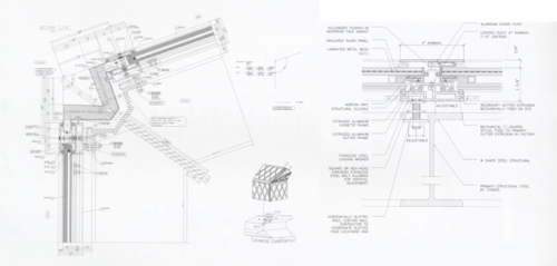
This representation is composed of four orthogonal view drawings, two and three dimensional, which combined enumerate different components of the façade in two distinct places, namely on the connection between two planes of the façade and on the connection to the structure. The smaller images situate the detailed sections on the building’s envelope, while the larger images describe them.
The larger images represent an imaginary section and detail the intricate joints of the façade. Two components can be seen in these sections, specifically the drawn and the written information. Having as basis an abstract image, the names, dimensions and drawing conventions convert it into a precise representation of a buildable component. Without these elements, this drawing would be limited to the exercise of aesthetics (on which it also performs on its own right)and be outstripped of its functional meaning. If you can’t name it and you can’t measure it, you definitely cannot (accurately) build it. Like the map and the territory, these sections are frequently scaled one to one (when not bigger). Simulation is devised before the real; in these drawings we observe a generation by models of a real, which has been mapped before its existence, and whose ultimate goal is a physical reality.
plan
Published March 7, 2008 Uncategorized Leave a CommentTags: architect, construction, el croquis, interior, orthogonal, plan, print, professional audience, technical drawing
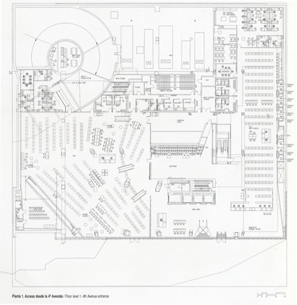
This representation depicts the first floor of the library, and like all plans, it is drawn from an imaginary point in space. This conceptual view, also known as “top view,” is based on the premises of a section plan, parallel roughly three feet above the plane depicted in the drawing, in a constructed orthogonal view, upon which everything shown in the plan is projected. This sort of representation is in many ways similar to code, as it is comprised by a specific language understood by architects and other building professionals but not easily understood by people outside the field. Nonetheless, untrained eyes can still discern a general idea of some elements here depicted (a notion of space, for example). Discernment of other elements like materiality and structural integrity require another level of training. Like code, the language of such plans is highly reliant on conventions and serves as a fundamental element of the design and construction process, as fluency enables architects and builders to establish communication and illustrate ideas. However, instead of being decoded into software operations or instructions on a computer, this simple two dimensional drawing is immediately converted into a three dimensional space, firstly in the minds of all the people involved in the design and (later) in the construction process. It is interesting to note how this plan makes visible the subtle interplay between the main program (in this case/plan, the children’s section) and the “dirty realism” often forgotten or erased in similar representations with a different audience, like the multiple directional structural columns punctuating the actual space.
graphic: program diagram
Published March 7, 2008 Uncategorized Leave a CommentTags: architect, concept book, conceptual, diagram, general audience, interior, orthogonal, section, web
This depiction of the library is comprised by a diagrammatic orthogonal cross-section and several differently expressed words reflecting the program, function and elements of the distinct levels of the building. This conceptual tool has various levels of information, not all of which are immediately apparent.
The more self-evident reading relates to the oddly serpentine form of the entire building, generated by the dislocation of the horizontal platforms from the building’s ground footprint.
The second level of information is suggested by the binary system of size and colors of the words that populate the diagram specifically establishing the distinction between areas of compartmentalized flexibility. Thus, areas where there is a high level of certainty of their evolution are specifically designed and enclosed in the floating boxes (represented by the larger and darker words), while other possibly more volatile functions are accommodated on their rooftops (represented by the smaller and lighter words).
Since the future of technology and its impact on the library typology is unclear, uncertainty was equated from the beginning in the design. The introduction of compartmentalized uncertainty, for which flexibility is required, tries to actively engage and manage in physical space the unpredictable change announced by the digital paradigm.
sketches: structural engineering
Published March 7, 2008 Uncategorized Leave a CommentTags: A+U, conceptual, construction, engineer, exterior, hand drawing, orthogonal, print, professional audience, section
These images depict the sketches used by the engineering team to test and quickly diagram the structural system and its different components. Although they can appear to be different reiterations of the same drawing, upon closer inspection by a trained eye (familiar with the building and with the engineering visual jargon) they are revealed as different drawings, which together explain the structural system as a whole.
The three drawings show the structure in distinct points of the building and emphasize its three components. The left drawing is a cross section, showing the concrete core which holds a part of the floating platforms and helps to stabilize the structure; the middle drawing is a side elevation reflecting the structural façade which also stabilizes the building laterally; the right drawing is another cross section explaining the principal system of transverse steel beams/columns supporting the dislocated platforms.
These simple sketches also reveal the importance of expressive and communicative free-handing drawing, regardless of the reliance on digital technology in the design and construction process. They also stress that man and machine are not competing but complementary elements. If the structure is going to be calculated by a computer, it was envisioned by a man, and in their cooperation innumerable possibilities are created.


